


Ref. No.:POWERPLANT200501
YEAR:2001 -2009
Brand:FOSTER WHEELER, SIEMENS, HONEYWELL ETC.
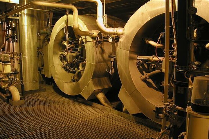
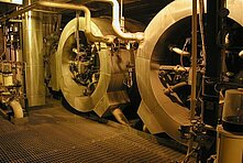
Qty:1 Second-hand power plant including boiler (BFB – boiler bubbling fluidized bed)
Built:2001, 2002, 2006, 2009 Revision
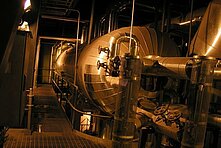
| Description | POWER PLANT INCL. BOILER - BOILER 88 MW - TURBINE 22.5 MW |
| Ref. No. | POWERPLANT200501 |
| Year | 2001 -2009 |
| Brand | FOSTER WHEELER, SIEMENS, HONEYWELL ETC. |
| Qty. 1 Second-hand power plant including boiler (BFB – boiler | bubbling fluidized bed) |
| Mfc. | Foster Wheeler, Siemens, Raumaster, YIT Corporation, Honeywell, |
| Built | 2001, 2002, 2006, 2009 Revision |
| BFB Boiler – 88 MW Steam turbine – 22.5 MW | |
| Main Steam Cycle | |
| BFB boiler K7 | |
| – Some parts removed and storaged indoor at the paper mill area | |
| – Boiler is made electrically safe (cables cut) | |
– Dry conservation ongoing since 2014 (tubes filled with nitrogen, dry air circulation) | |
| – Steam Turbine VP4 (in storage) | |
| Generator (in storage) | |
| Power Plant – Function | |
Primary function is to produce steam for the Paper Mill reliable and economically | |
| Secondary functions | |
| Burning of the Paper Mills (PM) waste wood | |
| Incineration of sludge from the PM | WWTP |
Production of flue gas to the PCC (precipitated calcium carbonate) plant | |
| Electricity production | |
| District heating production | |
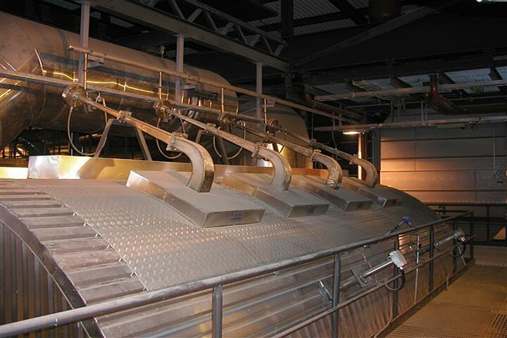
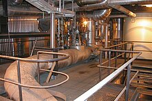
| Scope of supply - main machinery and key components | |
Feed water pumps and motors 2 pc High-pressure preheater, feed water heater | |
| Feed water valves Injection water system | |
| Steam drum Combustion chamber | |
| Fuel drop funnel 4 pc Start-up burners 2 pc | |
| Load burners 2 pc Waste oil burner, waste oil tank | |
| Natural gas filters Economiser | |
| Air-preheater Super heater | |
| Exhaust system Main steam valve | |
| Safety valves Dust removing system | |
| Bed material system, bed sand silo Bed sand preparing | |
| Bed lime system, lime silo Furnace ash system | |
| Fly ash system, fly ash silo and screws Primary air blower | |
| Secondary air blower Twist grip blower | |
| Bag filter Flue gas blowers 2 pc | |
| Flue gas scrubbers, lye system, scrubbers sludge system | |
| Safety locking system Nitrogen preservation system | |
| Chemicals dosage and chemical pumps Sample system | |
| Chimney | |
| Technical Data | |
| BFB-boiler K 7 | |
| Mfc. | Foster Wheeler Oy Commissioning |
| Heat Output | 88 MWth Steam parameters |
| Feed water temp. | 135-190°C Flue Gas Exit temp. |
| Boiler Efficiency | 88.5% SO2 Emissions |
| NOx | < 425 mg/Nm3 PM |
| Operation time | 88 000 hour Latest revision in 2009 (air preheater) |
| Maintenance revision annually Operation manual | |
| Main Fuels Bark, saw dust, wood chips and waste wood | |
| Sulphur <0,05% Moisture 30-65% LHV 3.7-6.9 MJ/kg | |
| Peat Sulphur 0.25% Moisture 40-58% LHV 6.3-11.3 MJ/kg | |
| Sludge from WWTP | |
Sulphur 0.2 – 1.7% Moisture 65-75% LHV >0.5 MJ/kg max. 7% of fuel power | |
| BFB Boiler K7 - Flue Gas Treatment | |
| Bag Filter Mfc. | Alstom 4 chambers |
| 376 bags 7 m long | |
| DAS (Dry Absorption System) Pre-coating with Ca(OH)2 | |
| Max. operating temperature 200 °C | |
| Flue Gas Scrubber Mfc. | Ehox Tuote |
| 2 scrubbers - 1 in operation 27 Nm3/s, 170°C in | |
20 Nm3/s, 43°C out Heat Recovery 18 MW at low temperature, 60°C | |
| Solid fuel system for K7 (NOT ALL AVAILABLE BY THE OWNER) | |
| Mfc. | Raumaster Built |
| Maintenance revision annually Operation manual | |
| Excluded | Not available by owner |
| Bar conveyor Crusher Fuel batching screw, fuel-receiving pocket | |
| Scraper conveyor to screen hall Screen system | |
| Scraper conveyor to silos and scraper conveyor on the silos | |
| Peat silo, fuel-batching screw (batching screw not existing) | |
| Bio fuel silo, fuel batching screw (batching screw not existing) | |
| Fuel line from silos | |
| Included | |
| Fuel line 1 from SFS to the boiler Fuel line 2 from SFS to the boiler | |
Back-up fuel pocket and fuel batching screw Fuel batching screw at power plant | |
| Robbery fuel batching screw Batching bin 2x50 m3 | |
Scraper conveyor at the boiler 2 pc Fuel batching pockets & fuel batching screw | |
| Fuel feeder 4 pc Fuel sample crusher | |
| Extinguishing steam system | |
| Sludge system for K7 | |
| Built | 2002 |
| Excluded | Not available by owner |
| Compressor Sludge pneumatic press | |
| Sludge pipe cleaning system Blowpipe to the power plant | |
| Included | |
| Cyclone Sludge silo and batching screw | |
| Automation and electrical equipment, spare parts for K7 | |
| Included | |
| Mfc. | Honeywell Type |
| Field instruments (as it is on the field) Motors | |
| Frequency changers Automatic valves etc. (as it is on the field) | |
Auxiliary devices (as it is on the field) All available existing specific spare parts | |
| Excluded | |
| Radioactive sources | |
| Steam Turbine/Generator VP4 (removed & in storage) | |
| Turbine | |
| Mfc. | Siemens Type |
| Power | 22.5 MW Reactive power |
| In operation since 2009 until 2012 Operation time | 24 000 h |
| Revolution | 8274 RPM Inlet pressure |
| Inlet temp. | 525 °C Inlet flow |
| Tap-off pressure | 3.7 – 24.1 bar Tap-off temp. |
| Tap-off flow | 7.9 – 33.5 kg/sec. Outlet pressure |
| Outlet temp. | 144 – 205 °C Outlet flow |
| Operation manual | |
| Generator | |
| Mfc. | Siemens Teho Generation AG Type |
| Nominal output | 28.5 MVA Power |
| Voltage | 6.3 kV (+5/-10%) Rated current |
| Frequency | 50 Hz In operation since 2009 until 2012 |
| Operation time | 24 000 h Operation manual |
| Included | |
| Turbine Gearbox Turning gear Generator | |
| Generator cooler Oil system Siemens automation system | |
| Automation and electrical equipment (as it is on the field) | |
| Motors Frequency changers Valves | |
Auxiliary devices (as it is on the field) All available existing specific spare parts | |
| Water treatment system at the power plant | |
| Mfc. | YIT Built |
| Raw water purification and desalination Operation manual | |
| Raw water purification | |
| Max capacity | 146 m3/h Capacity |
| Included | |
| Pumps and compressors Tanks | |
| Flock-filtering system 2 pc Preheater of raw water | |
| Automation and electrical equipment (as it is on the field) | |
| Motors Frequency changers Valves | |
Auxiliary devices (as it is on the field) All available existing specific spare parts | |
| Desalination | |
| Net capacity | 2 x 72 m3/h |
| Included | |
| Cation exchangers 2 pc A1/A2 exchangers 2 pc | |
| MB exchangers 2 pc Tanks | |
| Pumps Heat exchanger | dilution water of lye |
| Automation and electrical equipment (as it is on the field) | |
| Valves Motors Frequency changers | |
Auxiliary devices (as it is on the field) All available existing specific spare parts | |
| Steam, condensate and feed water system | |
| Included | |
| Feed water tank Condensation tank | |
Purification of condensation, precoat-system Condensed steam pumps | |
| Steam tanks Steam condenser | |
| Reduction valves Steam-pressure accumulator | |
| Cooling water system | |
| Automation and electrical equipment (as it is on the field) | |
| Valves Motors Frequency changers | |
| Common electrical equipment | |
| Process central | |
| Distribution transformers | |
| 1 pc 400 V 1.25 MVA 2 pc 690 V 3.15 MVA |