


Ref. No.:MELTSLABSTRIPCASTL170601
Brand:Demag (GHH), BSE, SMS, SIEMENS, M&W
Capacity:600,000 TPY
Built:1985, 1998, 1999, 2001 Revamped: 2009 & 2011 by BSE & ABB
Qty. 1 Second-hand steel melt shop plant including slab, strip casting lines, rolling mill and slag processing plant
Mfc.: Demag (GHH), BSE, SMS, SIEMENS, M&W Built: 1985, 1998, 1999, 2001
Revamped: 2009 & 2011 by BSE & ABB Stopped: 12-2013
Slab Dimensions: Width: 800-1.600 mm Thickness: 150, 175, 210, 240 mm
Max. Length 12.000 mm Machine radius: 9800 mm
External hot rolling process! Dim.: 800-1600 x 4 – 6 mm thickness
Strip Caster - dimensions: Width 1130 + 1450 mm Thickness: 1.8 – 6.0 mm
Rolling mill - exit: Width: 1130 – 1450 mm Thickness: 1.5 -2.5 mm
Capacity: 20 melts/day - 600,000 T/annum
Main operating voltage: 500 V, AC Control voltage: 230 V AC, 24 V DC
Consist of:
Scrap storage device UHP Electric Arc Furnace AOD Converter System Secondary Metallurgy Continuous Slab Casting Plant Miscellaneous Overhead Cranes Dust Removal System Strip Casting Plant 4-Hi Rolling Mill Flying Shear Cross Cut Shear Slag Processing Line
Technical Data
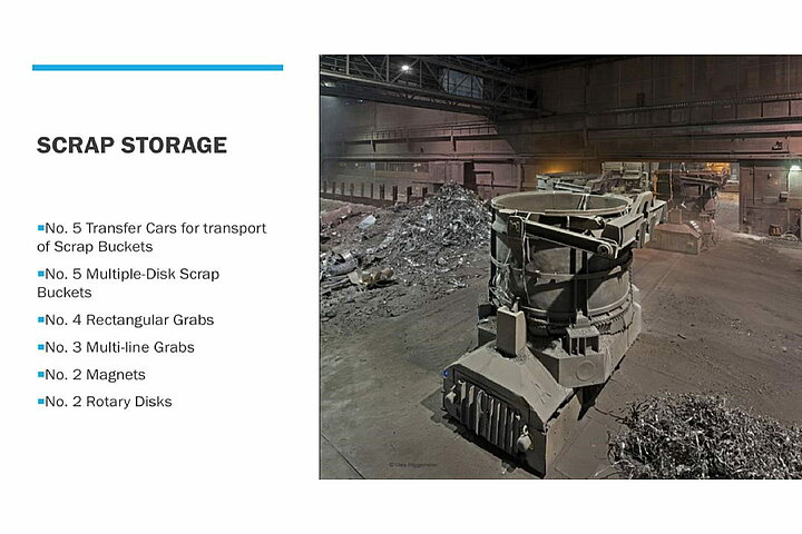
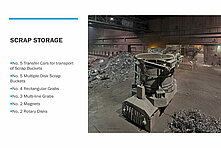
SCRAP STORAGE DEVICE
• (5) Transfer Cars for transport of Scrap Buckets • (5) Multiple-Disk Scrap Buckets
• (4) Rectangular Grabs • (5) Multi-line Grabs • (3) Clamshell Grabs
• (2) Magnets • (2) Rotary Disks
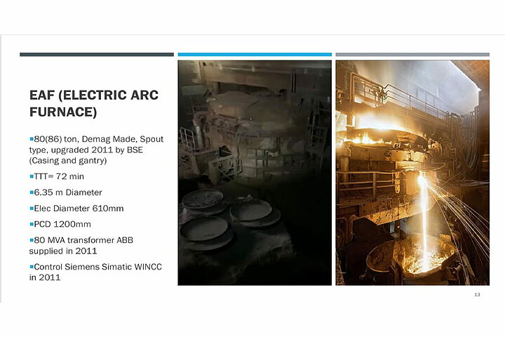
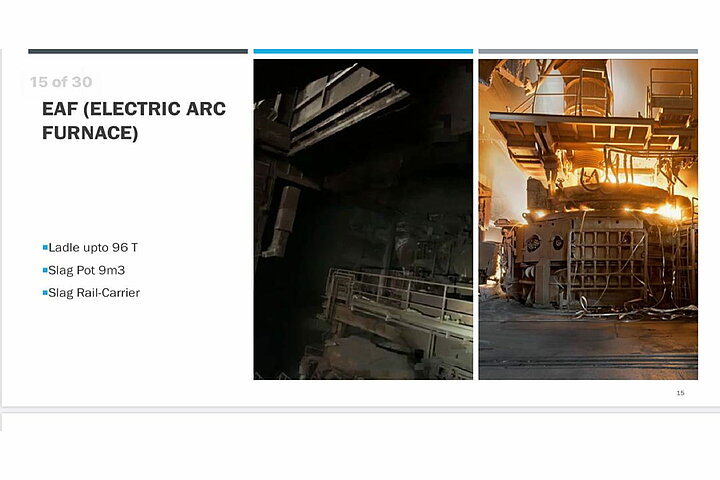
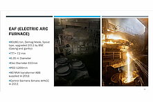
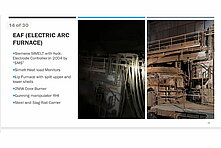
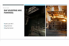
UHP ELECTRIC ARC FURNACE
• Mfc.: DEMAG Capacity: 80 (86) Ton Diam.: 6.35 Meter Built: 1998
Electrode Controler Converted to Hydr. and in 2011 new furnace rocker, casing and gantry
installed by “BSE” and in 2011 new 80 MVA Transformer supplied by ABB
Design rating 80 – 80 – 56.6 MVA
Rated voltage / Design ratio 25kV / 849 – 704 – 498V
Design current Prim.: 1848 – 1848 – 1306A Sec.: 54.4 – 65.6 – 65.6 KA
Control SimaticWinCC (2011), Siemens SIMELT,
Hydr. Electrode Controler (2004) “SMS”: Simelt-Nec Heat Load Monitors;
Lipp Furnace with with split upper and lower shells Conventional
Tilting Casting Diam.: 6.35 M Electrode diam.: 610 mm
diametral pitch 1.200 mm Fore-Blow approx.: 250 Nm Oxygen on Si
Cooling Wall and Cover Tap-to-Tap Time: 72 Min. Product Range 100%
Stainless Steel Types
• Hot Steam-Cooled Furnace Swivel Arm
• 2 MW Door Burner (natural gas/oxygen) and Oxygen Lance Manipulator
1 1/4” Pipe Max. flowrate: 2.100 Nm³/h
• Gunning Material Manipulator ”RHI” with Silo (2005)
• Steel and Slag Rail-Carrier, holding Decanting Ladle (96 Ton) and Slag Pot (9 M³)
• Slag Rail-Carrier
Electric furnace control system
B&B system environment Simatic WinCC
User software programming Hellingrath
Hardware and software modernization BSE in 2011
PLC basic automation of electric furnace
User software programming Hellingrath
Year of manufacture of automation system 1999
PLC 1 – S7 400 Furnace hydraulics, furnace, gantry and cover movements, furnace
monitoring systems, smelting controller, transformer stage switch
controller, transformer cooling, reading of transformer
measurements, steel works computer communication (L2)
PLC 2 – S7 400 Secondary units, vehicles -steel and slag carriage/, furnace housing,
movements of direct extraction arm, electrode adjustment device,
O2 lance, door burner, lance and burner manipulator, reading measuring,
control and regulating values for the furnace, high speed relaxation
equipment for the hot cooling system
PLC 3 – S7 400 Furnace wall and cover cooling system, circulating pumps, feed water
pumps, condensate and feed water return pumps, measuring, control and
regulating equipment cooling and steam flashing drum
PLC 4 – S5 95F Steam flashing drum safety controller
Siemens SIMELT electrode controller
Supplied and programmed by Siemens SIMELT
Year of manufacture of automation system 2004
Electrode controller - S7 400 SIMELT AC
Operating point enhancement SIMELT NEC
Smelting controller SIMELT MDC
B&B system for SIMELT Siemens WinCC -V6.0 SP2/ on Siemens 19” Rack PC
Old systems are available on standby if the Electrode controller system ‘ABB', smelting controller
SIMELT fails for the basic ‘Hellingrath’ automation system
The estimated weights:
1. UHP – furnace 380 Ton 2. Furnace transformer 120 Ton
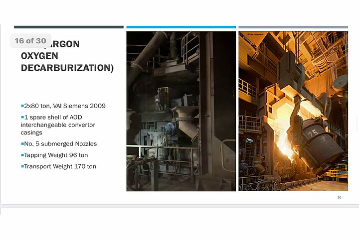
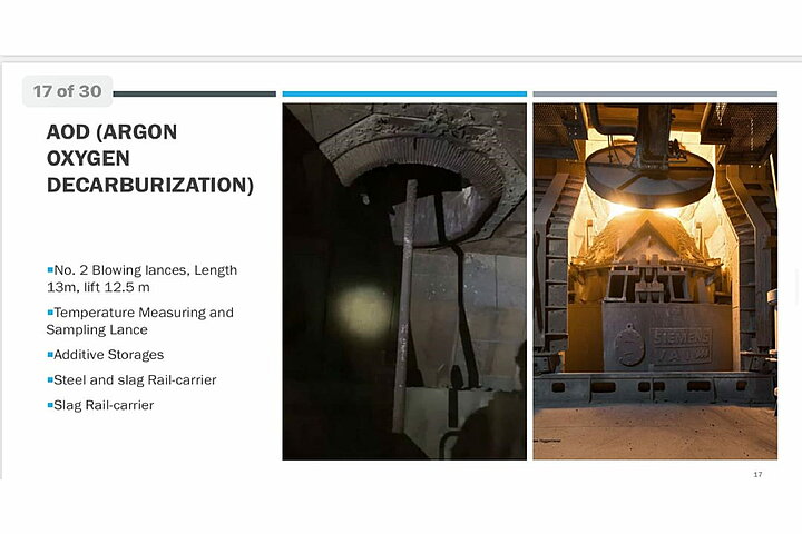
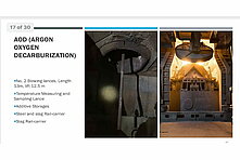
AOD CONVERTER SYSTEM
• (2) SIEMENS VAI AOD Converters revamped in 2009
interchangeable converter casings converter trunnion
rings with cooling system new converter bearings and stands
new tipping gearbox incl. drives new converter casing
entire valve station exhaust manifold hoods
new charge hoppers converter change rail-carrier
extraction system. Controls “Siemens” Simatic PCS 7 (2005)
• Converter Vessel, AOD Process with (5) submerged nozzles
Volume 88 M³ (excluding lining) 46.5 M³ (new lining)
Tapping weight max. 96 Ton, Transport Weight (including lining) 170 ton.
• Converter Trunnion Ring water cooled-trunnion ring
• Converter Tipping Drive • Valve Station for Process Gasses
• (2) Blowing Lances, Length 13 M, Lift 12.5 M
• Temperature Measuring and Sampling Lance (Sub-Lance)
• Additive Storage and Supply System • Exhaust Hood and Cooling Stack
• Converter Doghouse
• Converter Changing Rail Carrier, Payload 170 Ton, Speed 10 M/Min, Hydr. Lift.
• Steel and Slag Rail-Carrier, Load 190 Ton, Speed 25M
• Slag Rail-Carrier • Converter Lining Stand
Electrics and control
Main operating voltage 500 V AC Control voltages 230V AC, 24V DC
Main drives for AOD converter system:
Tipping drive for converter 1 2x Mill motors, 520 V, 665 rpm, 73.5 kW each with 4Q Simoreg
DC Master electronic power converter (Emergency operation with one drive is possible)
Tipping drive for converter 2 2x Mill motors, 520 V, 665 rpm, 73.5 kW each with 4Q Simoreg
DC Master electronic power converter (Emergency operation with one drive is possible)
Tipping drive for converter break-out stand 2x Mill motors, 450V, 750 rpm, 58.5 kW each with
4Q Simoreg DC Master electronic power converter
Main cooling water pumps (hood cooling) 2x 110 kW (2 drives per converter)
TP lance winch drive 520 V, 1120 rpm, 105 kW
DC electronic power converter drive
O2 lance winch drive 2x 30 kW Simovert Masterdrive with chopper (1 drive per converter)
Control system for AOD converter system:
B&B system environment Simatic PCS7 User software programming Siemens
Year of manufacture of automation system 2005
Software version Siemens PCS7 V6.0
Server hardware version 19” Fujitsu Siemens server PRIMERGY TX300
2 Xeon DP processors with 3.2 GHz
Clients hardware version 19” SIMATIC PCS7 OS client IL 40S V2
Pentium 4 processor, 2.8 GHz
Engineering station hardware version 19” SIMATIC PCS7 ES/OS server IL 40S V2
Pentium 4 processor, 2.8 GHz
Server 2x (redundant)
Clients 10x. (3x control stand for converter 1’, 3x control stand for converter 2’, 1x operating
diagram input, 1x control stand for ladle firing system, 1x alloy material management,
1x switchgear)
Engineering station 1x (for PCS7, Step7, S7 Graph)
PLC basic automation of AOD converter system:
User software programming Siemens Automation system modernisation 2005
Media system for converter 1 - S7 400 Controller / Regulator blowing media -O2, N2, Ar,
compressed air/ for floor nozzles and lance
Media system for converter 2 - S7 400 Controller / Regulator blowing media -O2, N2, Ar,
compressed air/ for floor nozzles and lance
Tipping drives for converter 1 - S7 300 Tipping drives for converter 1
Tipping drives for converter 2 - S7 300 Tipping drives for converter 2
O2 lance for converter 1 - S7 300 Lift and lateral movement of O2 lance
O2 lance for converter 2 - S7 300 Lift and lateral movement of O2 lance
TP lance – S7 400 Lift and lateral movement of TP lance, sleeve manipulator
Cooling systems - S7 400 Pump controllers, hood cooling system, exhaust duct cooling
system, converter heat maintenance firing system, communication with external water
management system
Alloying system - S7 400 Material withdrawal from overhead bunker, with conveyor
belts, charge bunker, weighing systems for weighing bunker and direct removal bunker
(Sirwarex), controller large displays
Low level bunker – S7 400 Material withdrawal from low level bunkers, with conveyor
belts, weighing systems for overhead bunker (Sirwarex), controller large displays
Coupling PLC – S7 400 Process controller converter operating diagram -media and alloys/,
communication with steelworks computer (L2), communication with peripheral systems –
dust extraction and water management/, immersion temperature measurements
Converter ladle firing system - S7 400 System controller for 2x converter ladle firing
systems (for ladles on steel transfer carriages) & for 6x freestanding ladle firing systems
Break-out stand - S7 400 Tipping drive for converter break-out stand, drives for 2x
converter carriages, controller for 2x converter heating firing systems
Converter changing carriage – S7 300 Hydraulics, drives, star wheel bearing movements (remote control: Theimeg)
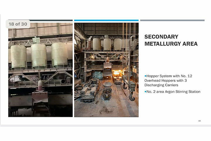
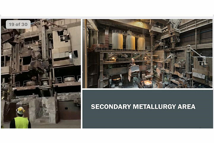
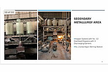
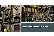
SECONDARY METALLURGY
• Hopper System (12) Overhead Hoppers with 3 Discharging Carriers
• Argon Stirring Station (2) stirring areas
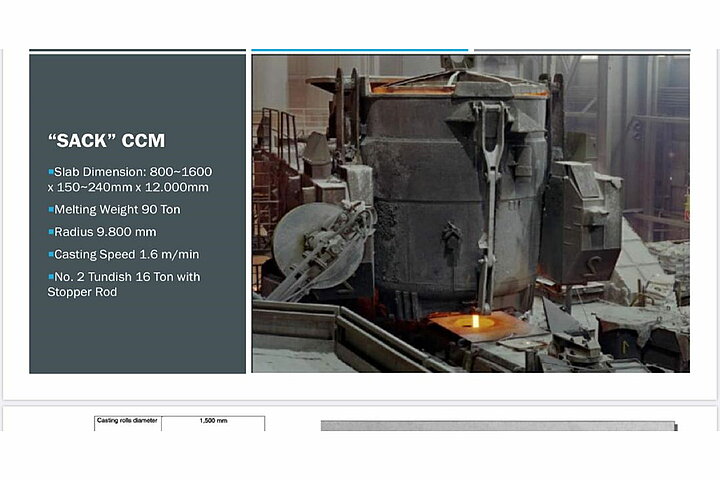
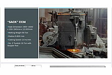
“SACK” CONTINUOUS SLAB CASTING PLANT
The plant was commissioned in 1981. Originally, block formats were also produced in the plant in addition to slabs.
Technical data: Machine radius 9,800 mm
Slab dimensions Thickness: 150 – 240 mm Width: 800 – 1600 mm
Possible slab length Max. 12,000 mm Melting weight 90 Ton
Height of the casting plant Top of roller table above steelworks floor 750 mm
Top of casting platform: + 11,300 mm Casting speed: max. 1.6 m/min
• Controls Siemens PCS-7 (2002)
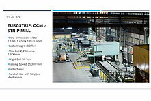
• Slab Dimensions: 800-1.600 x 150 - 240 mm Max. Length 12.000 mm
• Melting Weight 90 Ton Radius 9.800 mm Average Casting speed: 1.0 M/Min.
• Ladle Turret: for (2) Ladles
• Ladle Shroud Manipulator Length 900 – 1.200 mm
• Tundish Turner (2) Max. Charge 16 Ton Turning angle 180°
• Stopper Rod “ Zimmermann & Jansen” • Heating Fire System for Tundish
• Mold Casting radius: 10.750 mm Width: 800 -1.600 mm x thickness 175, 210, 240 mm
• Mold Lifting Table • Segments 1 Total No. of Rollers 24
• Segments 2-15 • Intermediate Roller Table
• Flame Cutting Machine with Roller Table
• Exit Roller Table with Emergency Slab Discharge
• Walking Beam Coolant Bed • Dummy Bar System
• Stamping and Marking Unit • Workshop for Mold and Segments
• Tundish Shop
Electrics and controller
Main operating voltage: 500 V AC DC converter drive supply rail: 400 V AC
Control voltages: 230V AC, 24V DC
Continuous casting system main drives:
Continuous casting drives 20 x DC motors each with 4Q Simoreg DC Master electronic
power converter
Mold lifting table DC motor with 4Q Simoreg DC Master electronic power converter
Distributing launder turner 2x DC motors each with 4Q Simoreg DC Master electronic
power converter
Spray cooling pressure increase pumps 2x DC motors each with 4Q Simoreg DC Master electronic power converter
Dummy bar winch DC motor with 4Q Simoreg DC Master electronic power converter
Dummy bar carriage 2x DC motors -1x chain transport, 1x drive/ each with 4Q Simoreg DC Master electronic power converter
Hydraulic pumps Various Cooling water pumps Various
Continuous casting plant early breakdown detection system
Supplied and programmed by Siemens BOPS
PLC system: S7 400 B&B system: PCS7 V5.1
Communication Basic automatic, steelworks computer (L2)
Continuous casting control system
B&B system environment: Simatic PCS7 User software programming: Siemens
Year of manufacture of automation system 2002
Software version: Siemens PCS7 V5.2 SP1
Server hardware version Dual processor workgroup server PRIMERGY B210 1 x
Pentium III 933 MHz -1 GHz
Clients hardware version SCENIC L, (D1219-A) Intel PIII 933 / 133, 256 SLC
Engineering station hardware version SCENIC L, (D1219-A) Intel PIII 933 / 133, 256 SLC
Server 2x (redundant)
Clients 3x control stand (of which 1x multi-client together with early breakdown detection system), 1x casting panel (touchscreen), 1x burner control stand, 1x switchgear
Engineering station 1x
Continuous casting system PLC basic automatic
User software programming Siemens
Automation system modernisation 2002
Casting machine PLC – S7 400 Ladle turning tower / hydraulics, distributing launder turner,
mold lifting table, system hydraulics, leak and pipe burst monitoring, section drives, load compensation regulator, route monitoring system, clamping hydraulics for segments, section control for contact pressure hydraulics, grease lubrication system, spra lubrication system, ladle slide hydraulics, roller tables, crop discharge, walking beam bed, dummy bar winch, communication with dust extraction system
PLC for casting level control – S7 400 Dr. Dr. Ladle slider control, stopper rod hydraulics
Berthold casting level measuring system casting level control, automatic casting on
Water management PLC – S7 400 Mold cooling, spray cooling, control / regulation of spray
plan / zones, sealed machine cooling system, temperature and volume control, pump
and fan controls
Flame cutting machine PLC – S7 300 System controller
Stamping machine PLC – S7 300 System controller
Dummy bar carriage PLC – S7 300 System controller
Distributing launder heating system PLC – S7 300 System controller
Continuous casting plant weight: The estimated weight is approx. 2600 Ton.
NOTE: EXTERNAL HOT ROLLING PROCESS!
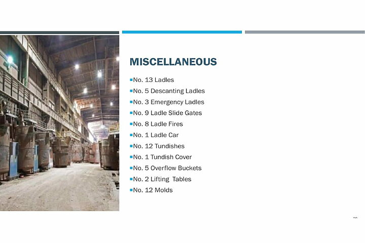
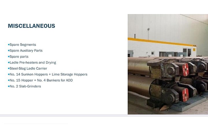
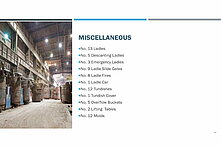
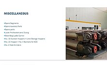
MISCELLANEOUS
• (13) Ladles + (5) Decanting Ladles + (3) Emergency Ladles
• (9) Ladle Slide Gates + (8) Ladle Fires + (1) Ladle Car
• (12) Tundishes + (1) Tundish Cover + (6) Overflow Buckets
• (2) Lifting tables • (12) Molds • Many Segments
• Many Auxiliary Parts • Spare Parts
LADLE SERVICE AREA
• Ladle Fires and Drying Fires • Steel-Slag Ladle Carrier
HOPPER SYSTEMS
• (14) Sunken Hoppers • Lime Storage Hopper
• Hopper System AOD (15) Hoppers and (4) Bunkers
SLAB GRINDING SHOP
• (2) Slab-Grinders “Wilhelm Schlüter” Length: 4000-9.800 mm x width 380/800-1.600 mm
Thickness 80-250 mm Weight: 20/32 Ton Motors: 250 kW
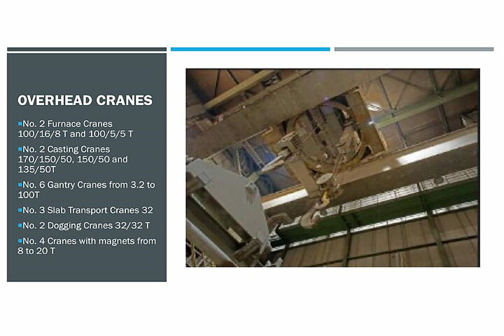
OVERHEAD CRANES
• (2) Furnace Cranes 100/16/8 Ton and 100/5/5 Ton
• (3) Casting Cranes 170/150/50 150/50 Ton 135/50 Ton
• (6) Gantry Cranes from 3.2 to 100 Ton • (3) Slab Transport Cranes 32 Ton
• (2) Dogging Cranes 32/32 Ton • (4) Cranes with Magnets from 8 to 20 T
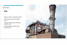
DUST REMOVAL SYSTEM
• Electric Filters Capacity: 850.000 M³/h
• Dry Dust Removal Capacity: 335.000 M³/h
• Sunken Hopper Dust Removal Capacity: 45.000 Nm³/h
• Lime Hopper Dust Removal Capacity: 15.000 N/m³
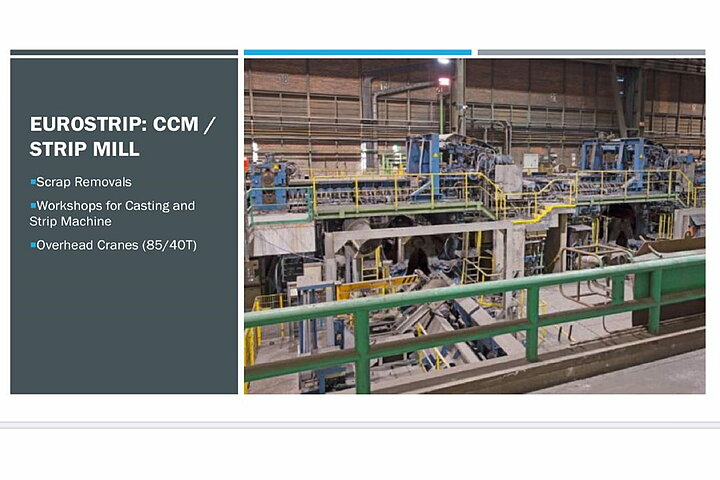
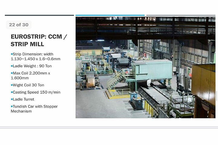
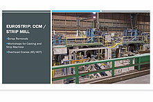
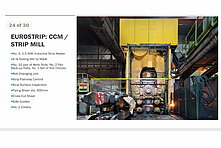
STRIP CASTING PLANT
Mfc.: VAI (VOEST ALPINE INDUSTRIEANLAGEN) Built: 1999
Strip dimensions: Width 1.130 + 1.450 mm Thickness 1.8 – 6.0 mm
Max. Coil dimensions: OD: 2.200 mm x width 1.600 mm Coil weight: 30 Ton
Casting Speed: 150 M/Min Rolling Speed: 200 m/min.
Fully Automated 1999 and 2013
Melt weight: 90 tons
Construction dimensions of strip casting plant
- Roller table via mill floor line: Approx. 800 mm - Casting platform: 3500 mm
Plant length: Approx. 90 m
Mechanical equipment
Ladle Turret - Manufacturer: "VAI"
- Intake of two ladles of each approx. 160 tons, rotation radius 5.000 mm
- Over-all rotation radius turret approx. 7.500 mm, 360° in both directions
- Ladle weighing
- Single stroke of the ladle carrier arms – maximum 1.000 mm
- Rotary motion: unlimited - Drive power 45 kW
- The ladle slide gate hydraulics are located within the ladle turret
- Emergency drive
Shroud Manipulator
- Manufacturer: "VAI" - Hydraulic Operation
- Shroud length: approx. 900 – 1000 mm
- Inertization possible - Replaceable fork
• Tundish Car - Manufacturer: "VAI"
- Intake of tundish: - Tundish weight: 13 tons
- Maximum melt: 16 tons
- Rail length: approx. 9 meters, stroke approx. 750 mm
- Weighing facility
- Continuous temperature rating by heating box probe
- Auxiliary facility: Infeed station / Infeed block for tundishes
• Stopper Mechanism Mfc.: “Zimmermann & Janssen”
- Deformation and motion: hydraulic
• Heating Fire for Tundishes and Immersion Tube Mfc.: “ MAPEKO”
- Tundish heatingup to: 1.200 °C - Natural gas burner
• CASTING MACHINE 2-Rolling System with (8) Casting Roll Pairs; (2) Casting Frames
- Machine execution: - Casting width: 1130 mm -1450 mm
Casting Rolls
- In total 8 casting roll pairs, several widths, including fittings like inserts warehouse etc.
- 2 pairs 1130 mm, 1 pair 1330 mm, 1 pair 1390 mm, 4 pairs 1430 mm
- 1 pair spare jackets for 1430 mm
- Rolls Ø 1480-1520 mm - Water-cooled up to 8000 l/min/Roll,
- Electrical drive - Surface cleaning system
Inertization-Cover
- 14 zone-inertization with each 2 gas connections,
- Total volume max. approx. 400 Nm³/h - Covers for several widths H1130, 1330, 1430 I
Side Sealings
- Three complete structures compatible among each other
- Rotative and vertical possibility for oscillation via hydraulic
- Hydraulic screw-up and multiple possibilities of adjustment
- Heatable on both front and back side up to 1300°C within several zones
Casting Frame
- 2 casting frames, compatible among each other
- Quick-change frame including all media connections
- Approximate weight: 85 tons including casting rolls
- Approximate dimensions: 5 m*3.5 m*1.5 m
Metrology
- Solution level rating via mould level camera
- Temperature scanner (company Land) within heating box, in front and behind rolling stand
- Strip controlling camera within heating box
• Heating Box and Roller Table (approx. 25 Rolls)
- Approx. 25 roller table rolls Ø 280 mm, individually driven, water-cooled, for strip widths
up to 1600 mm
- Heating box fire-proofed covered, water-cooled panel,
- Heating box inertizable with up to 3.000 Nm³/h N2 HO2 < 0,5%I
- Ribbed table for strip guide, hydraulically shiftable
• Steering Driver
- Ø 600 mm, for strip widths up to 1600 mm, width of action 1100 mm, Electrical drive
- Hydraulically shiftable: vertical and bow-type shaped
- Connected to visual strip flow control (company Eckelmann )
• (2) Strip Thickness Gauges Mfc.: “MESACON”
- Manufacturer: “Mesacon”
- Strip thickness- and strip profile gauges in front as well as behind rolling stand
- Each 4 X-ray generators with 32 channels, maximum width approx. 1400 mm
- Axially shiftable, bow-type shape C
• Four-Roll-Driver; Vertical Rolls hydraulic shift.
- Ø 400mm, vertical rolls hydraulically shiftable, rolls hydraulically shiftable, roadway 180 mm
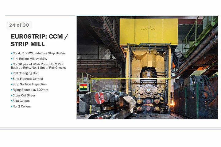
• Inductive Strip Heater Mfc.: “ELOTHERM”
- Four modules of each 2.5 MW
- Module axially and vertically shiftable in order to adjust temperature and temperature
distribution - Maximum temperature stroke: approx. 400 K
• 4-Hi ROLLING MILL Modernised: 2001 by M&W
Roll Bending (10) Pair of Work Rolls (2) Pair of Back-Up Rolls
(1) Set of Roll Chocks. Roll Changing Unit
- Drive capacity: approx. 5.5 MW, pinion gear unit, speed max. approx.: 200 m/min
- Maximum rolling load: approx. 45 MN - Hydraulic screw-down
- Backup rolls Ø1350 mm – 1450 mm working rolls Ø 700 mm – 750mm
roll body length 2250 mm
- In total 10 pairs of working rolls including roll chocks - 2 pairs of backup rolls
- 1 set of roll chocks for backup rolls
- Roll chocks for backup rolls: with Morgoil bearing
- Positioning elements: axial roll shifting HCVCI +-120 mm, roll bending 3.000 kN,
35 zone cooling
- Roll gap lubrication
- Various regulations: for example visual strip flow control with steering driver
(company Eckelmann)
- Roll changing device (also suitable for change on the fly)
• Strip Flatness Control Mfc.: “IMS” Adjustment by “BFI”
- Visual strip flatness rating system with projectors and cameras
- Flatness adjustment via positioning elements of the rolling stand
• Roller Table Mnf.: “M+W”
- Each roll individually driven, and water-cooled - In total 22*6 rolls Ø220 mm
- Length of rolling stand up to 1st coiler approx. 47.5 m,
- Laminar cooling between rolling stand and coiler
• Strip Surface Inspection
OIS – Parsytec” (exit line, roller table)
- System specification: - HTx 4.3 “Parsytec”
- 5 CCD- cameras for strip surface (inspection width =1730 mm)
- Picture resolution: 0.5 mm x 1.25 mm / Pixel
- 3 lightings - 4 computers in network
- All devices with one place of work within container
- Inspection capacity:
- 20 strip casting plant-specific types of defects including 50 variations of defects
- Online-alarms
- Offline applications: Assessment, Gussmap, testbed for post-classification
- Documents:
- Master Sets of Samples (MSoS) - Programs for post-classifications
- Systems document (HTx4.2) of “Parsytec”
OIS – Pieper”: (Heating box, situated below casting rolls)
- System specification:
- Camera for strip bottom side (Width of inspection=140-220 cm)
- Picture resolution: approx. 3 mm x 3 mm / Pixel
- 1 PC
- Inspection capacity:
- 2 strip casting plant-specific markings (casting roll injuries)
- Documents:
- Source code in Matlab (co-owner: “Pieper” )
Other:
- Master sets of samples (2 for hot rolled strip, 2 for cold rolled strip) for the strip casting plant specific classifiers, 13-15 types of defects on the annealing- and pickling lines (GBL) of the cold-rolling mill
- Programs for post-classifications on the annealing- and pickling lines
• FLYING SHEAR Mfc.: “M&W” Diam.: 600 mm
- Hydraulically adjustable - Performance: drives the strip during a shearing cut
• CROSS CUT SHEAR Mfc.: “M&W” Max thickness: 5 mm (Stainless Steel)
- Drum shear-principle - Maximum strip width 1600 mm
• Side Guides - Shiftable - Wearing strips
• COILER Mfc.: “VAI” (2) Coilers Expanding mandrel
Coil ID: 725 mm Drive power: 200 kW each
Max. Coil weight: 30 Ton Coil OD: 2.200 mm
- Each coiler with 3 basket rolls Ø 380 mm, driver with top roll Ø 800 mm, bottom roll Ø 600 mm
- Capacity per each coiler 200 kW
- Maximum coil weight approx. 30.000 kg, max. coil outside diameter Ø 2.200 mm
- Coil transfer system per each coiler including coil strapping machine
- Length of coiler 1 – coiler 2: 9.7 m
• Scrap Removal
- Dummy bar pinch roll set, dummy bar coiler - Scrap driving gear
- Sample station - Emergency trap basket
• WORKSHOP for maintenance- and repair work of Casting Rolling Mill
Complete Maintenance and Repair Equipment with all required aligning stands for moulds and segments, as well as equipment for handling / repair / installation / dismantling of the individual power units of the strip casting machine
Electrical equipment and Control system
Control system strip casting plant:
B&B System environment, Visual display surface: WinCC 6.0, SP2
Used system families for control Step 7, TCS, LogiDYN, LogiCAD
Programming application software Basic system VATech / Elin as well as various
further developments (Water management Balcke Dürr / Löb)
Year of manufacture automation system 1999-2013
Communication HP Network technique, Industrial Ethernet 100MB/s – divided into PLC- (Processing-) Net and HMI- (Terminal-) Net Various Profibus systems
Hardware status Server HP ProLiant DL 380 G3 -Windows Server 20032
Hardware status Clients HP ProLiant DL 380 G3
Hardware status Engineering station HP ProLiant DL 380 G5
Software status Engineering station Simatic Manager: Step 7 V5.5 Stand V5.5.0.0
Beckhoff: TwinCAT v2.11.2220 PLC Control v2.11.0 System Manager v2.11.0
Server 2x casting machine G3, 2x Water management G3 (in each case redundant)
Clients Casting machine: 10 Clients: thereof 7 G3, 1 Dell, 2 19“
Touchpanels Water management: 2 Clients, (G3, Dell RS 5400)
Various PCs Various types of technological data logging, 2x IBA PDA systems,
various types of Engineering Station (2x TCS, Logidyn / Pilz)
PLC Basic Automation Strip Casting Plant:
Programming of user software Basic system VATech / Elin as well as various
further developments (Water management Balcke Dürr / Löb)
PLC 1 - S7 400 – 3 CPUs Master: Sequences, ladle turret including ladle slide gate
(Master, guide value, connecting rod) regulation, tundish cars, heating boxes, bucket
elevators, traversing drives inductors, casting roll cleaning, driver adjustments Guide value: Drives (including speed control of the line drives)
Connecting rod: Coupling with level 2
PLC 2 - S7 400 – 3 CPUs (AGC, KKSA, GSPR) AGC: Casting roll adjustment, monitor regulation, Compensation of eccentric and elongation
KKSA: F/v regulation (in the past mainly mould side sealing)
GSPR: Mould level control
PLC 3 - S7 400 - Media Media - Hydraulics, water circulations, industrial gases, lubrications
PLC 4 - S7 400 - Stand Auxiliary functions rolling stand, roll changing cars, working roll zone cooling
PLC 6 - S7 400 – Exit Line Sequences, control functions Exit-Line
PLC 7 - S7 400 – Side sealings Sequences, control functions side sealings, electric heating plant, hydraulic
2x PLC S7 300 – Coil tying machine 1/2 Plant controls
PLC S7 400 - Elotherm Plant control inductive strip heating plant
Pilz Programmable Safety systems 3056 Collision locking, ladle turret and tundish car
Beckhoff Embedded-PC CX - CX1030 CPU Sequences, technological functions and
regulations of the hydraulic axles (cylinder)
ALSPA C80-HPC Logidyn D2 Rolling converter, auxiliary functions rolling drive
VANTAGE rolling stand - VME BUS system 4x 7740 CPU´s: Technological regulating system
rolling stand, communication to Mesacon (profile sensors) and LAND
(Temperature scanning system)
VANTAGE Exit-Line - VME BUS system 3x 7740 CPU´s: Technological regulating system
Exit-Line
PLC S7 400 – Water management Plant control (Utility building) (construction level 1)
PLC S7 400 – ‚New‘ water management Plant control (Water management building)
(construction level 2 and 3)
Main drives strip casting plant:
Casting roll drives 2x200 kW (frequency converter)
Roller table rolls Approx. 180 drives 1.2 kW divided into 8 frequency controlled driving units
Rolling drive 5.5 MW (GTO pulse converter with active recoverable frontend)
Steering driver 2x30 kW (Frequency converter)
Cold rolled strip driver 2x37 kW (Frequency converter)
Scrap driver 2x37 kW (Frequency converter)
Four-roll unit 4x4 kW (Frequency converter)
Elotherm Inductive heating 4 Inductor module – supplied by 4 load converters with
each 2.5 MW capacity
Shear driver 2x 110 kW (Frequency converter)
Shear drive 250 kW (Frequency converter)
Coiler drive 2x2x 200 kW (Frequency converter)
Coiler basket rolls 2x3x 5 kW (Frequency converter)
Downcoiler mandrel 2x560 kW (Frequency converter)
Hydraulic Casting machine (Main hydraulic) 5x 75 kW
Casting machine (Servo) 2x 75 kW Rolling stand (160 bar) 3x 75 kW
Rolling stand (290 bar) 2x 90 kW Exit section 3 x 110 kW
Ladle slide gate 2x 15 kW
As well as various appropriates to recirculating and rotating pumps
Lubricant of circulating aggregates Pinion gear unit and Morgoil bearing
Cooling water – rotating pumps (completely Casting roll cooling 3 x 250 kW frequency-controlled) Machine cooling 2x 90 kW Inductive heating 2 x 110 kW
Rolling stand (closed) 3x 75 kW Rolling stand (open) 3x250 kW
Open circle (casting machine, run-in rolling stand,
Laminar cooling) 2x 90 kW Scale pit 1 3x 75 kW
Settling basin 1 3x 110 kW Coiler (closed) 2x 90 kW
Coiler (open) 2x 160 kW Scale pit 2 2x 15 kW Settling basin 2 2x 75 kW
As well as various appropriates to cooling tower and air cooling drivers
• Overhead Crane: 85/40 Ton • Water Treatment Plant