Ref. No.:SKINPASSMILL210301
YEAR:1985, 1986,
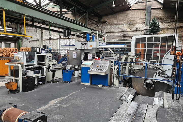
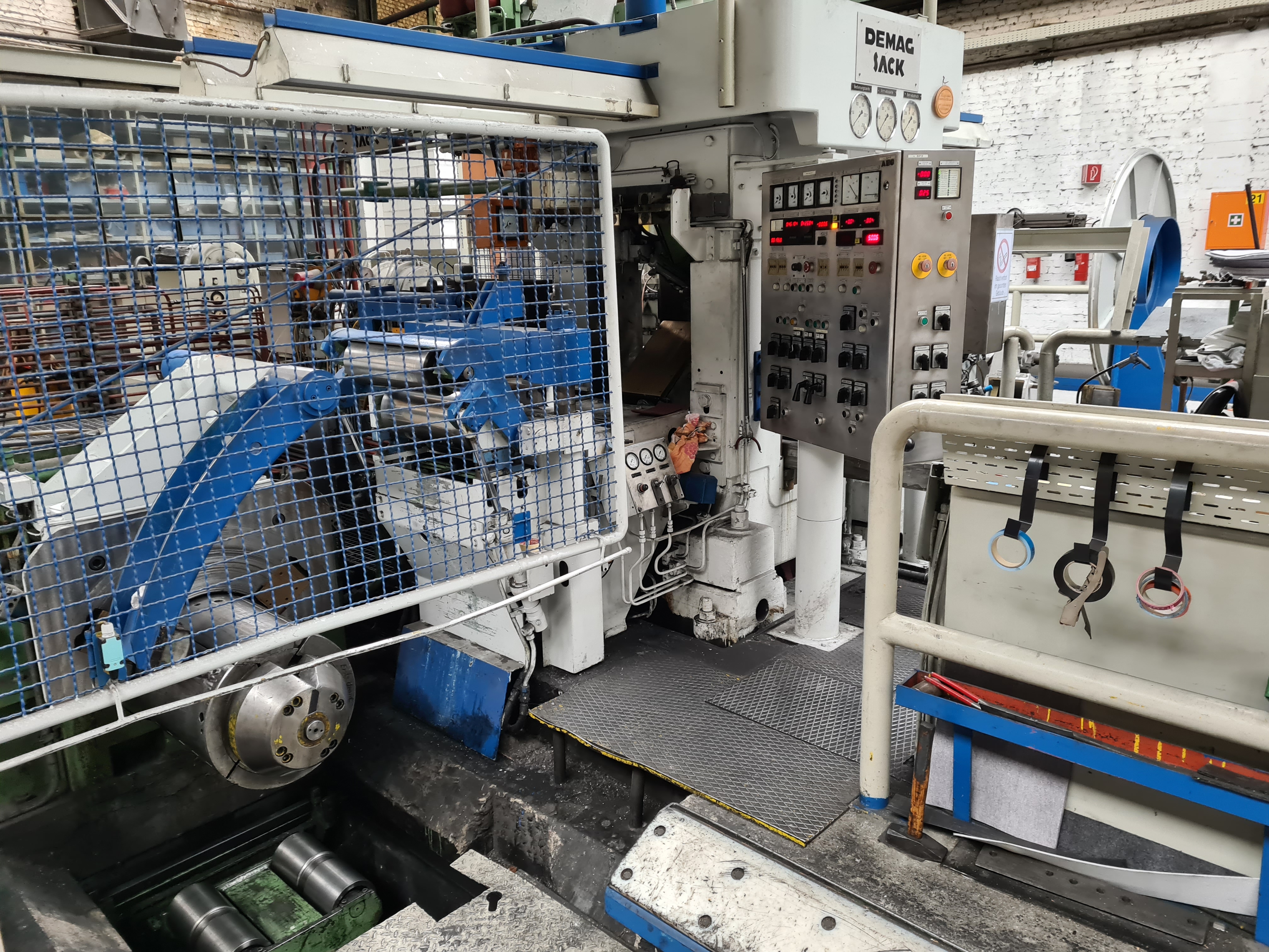
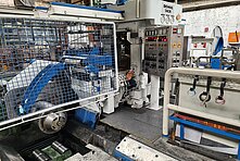
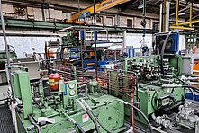
Qty:1 Second-hand skin pass mill
| Description | SKIN PASS MILL - DUO MILL - 80-470 MM - 4.0-0.2 MM |
| Ref. No. | SKINPASSMILL210301 |
| Year | 1985, 1986, 1993 |
| Brand | MANNESMANN DEMAG |
Qty. 1 Second-hand skin pass mill | |
| Mfc. | Mannesmann Demag Sack Built |
| Type | Duo Cold Rolling Mill – Non-Rev. Dia. 330 x 500 mm |
| Material | Carbon steel, cold rolled and annealed |
| Strip width | 80 - 470 mm Thickness entry |
Decoiler Modernised in 1986 | |
| ID | 400 with segments 500 & 600 mm Spreading range |
| Strip tension | 1300 – 65 daN Braking system |
| Braking torque | max. 1300 daNm De-coiling speed |
| Coil cross section | 20 – 1880 mm² Coil weight per mm strip width max. |
| Coil weight | 5.0 T Coil ID |
| Roll dia. | 300 – 330 mm Roll length |
| Roll force | 1850 – 2400 kN Min. roll force |
| Hydraulic roll adjustment Adjustment stroke | 80 mm |
| Adjustment speed | 1 – 3 mm/sec. Rolling speed |
| PLC system | Siemens |
| Coiler | |
| Coil ID | 400 mm with segments |
| Strip tension range I | 2500 – 25000 N Motor power |
| Strip tension range II | 500 – 2500 N Motor power |
| Gear ratio | i = 14.66 Lubrication |
Decoiler Modernised in 1986 | |
| ID | 400 with segments 500 & 600 mm Spreading range |
| Strip tension | 1300 – 65 daN Braking system |
| Braking torque | max. 1300 daNm De-coiling speed |
| Generator power | 2 x 16 kW Motors in parallel arrengement |
1 Motor can be decoupled by gear shifting | |
| Generator revolution | 0-405/2025 Transverse displacement |
Modernisation in 1993 | |
Hydraulic roll adjusting device | |
Adjustment by position and roll force-controlled hydraulic cylinder arranged on the stands. | |
Control via fast acting servo valves. | |
Strip thickness control | |
Consist of the electrical cubicle (1600 x 1600 x 600 mm) with all necessary supply units provided | |
for the following types of control | |
Position control Roll pressure regulation Return regulation (analog/digital) | |
Degree of skin pass measurement Degree of skin pass regulation | |
Qty. 2 Positioners Qty. 2 hydraulic-electric converters for measuring the rolling force | |
1 Exit guiding system (left side of the rolling mill) | |
The exit guide is equipped with the following devices | |
Base support with table top and places for tape thickness measuring device, tape greasing roller | |
and skin pass level measuring device, hydraulically adjustable folding table, hydraulically | |
operated crop shear with angled cut upper knife, loose deflection roll, bearing of the deflection | |
roll intended to accommodate a strip tension measuring device. | |
1 Oscillating cleaning device of the top roll | |
1 Oscillating cleaning device of the bottom roll Coiling station | |
| 1 Coiler shift gear | |
With 2 input shafts, helical gears, hardened and grinded, shafts mounted in roller bearings, | |
pneumatically operated gear shift stage for belt tension changeover, lubrication of the gear unit | |
by an attached oil lubrication pump, toothed clutches to connect the motors with the gear unit, | |
pneumatically operated disc brakes as idle brakes. | |
| 1 Take-up drum | |
In flange design, hydraulically operated, clamping device to grasp the beginning of the strip | |
separately controlled, cylinder with circumferential oil supply, cast steel attachment segments to | |
increase the diameter from 400 to 500 mm | |
| 1 Coil pushers | |
Hydraulically operated coil pusher with spring-loaded belt scrapers, attachment to the winding | |
gear, guide in round bars. | |
1 Strip pusher Hydraulically operated | |
| 1 Paper unwinder | |
For unwinding interlayer paper, winding shaft mounted in roller bearings, set up for tensioning | |
paper rolls, braked by a pneumatically operated disc brake | |
| 1 Coil lifting car | |
With hydraulically operated lifting and driving device as well as tilting device and movable pit | |
lock, coil holding device for narrow coils, hydraulically swiveling and hydraulically adjustable to | |
| strip width. | |
| 1 Coil magazin | |
For holding 3 coils of max. width and min. coil diameter of 800 mm, coil magazine made of | |
welded construction anchored in the foundation and provided with a polyamide or wooden | |
| support | |
| 2 Joint spindles | |
including rolls and pinion sleeves for driving the rolls, arranged between the pinion gear and | |
the rolls, support device for the joint spindles when changing rolls, the support is hydraulically | |
| operated | |
1 Hydraulic balancing for the above roll installation unit | |
1 Cushioning plate arranged in a tilting gutter for coil cushioning | |
4 Wear strips for mounting in the stand windows | |
16 Wear strips for the chocks | |
1 Transfer tables of the unwinding deflection roll stand | |
Shortening of the table and renewal of the hydraulic cylinder as well as attachment of a console | |
to accommodate the skin pass degree measuring device | |
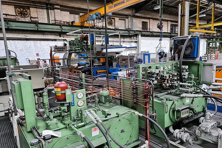
1 High pressure hydrauli aggregat | |
For supplying and controlling the adjusting cylinders, designed for an operating pressure of | |
250 bar, nominal pressure 315 bar, | |
the hydraulic unit consists of | |
oil tank, pump station and additional reserve pump, filter station and valve stand, the system is | |
internally piped, the valves are wired | |
1 Hydraulic aggregat with valve stand | |
To supply and control all hydraulic cylinders within the existing assemblies described above | |
(without unwinding station) | |
The unit is designed for an operating pressure of 100 bar, nominal pressure 120 bar and | |
| consists of | |
oil tank, pump unit and additional reserve pump, filter station and ventlistand, control by | |
electro-magnet valves, the system is internally piped and the valves are wired. |